An integrated digital workflow in development for large-scale sculpture production. It connects AI-assisted modelling and steel frame planning with 3D printing and assembly.
A sculptural model can look finished before its parts can be printed, joined, carried or installed. Moving a seam or changing the scale affects wall thickness, mounting points, steel lengths, tolerances and the order of assembly. VERKIVA Sculpture is being developed to keep those decisions together.
Three integrated systems.
Planned capabilities cover the geometry, the supporting structure and the work on the production floor.
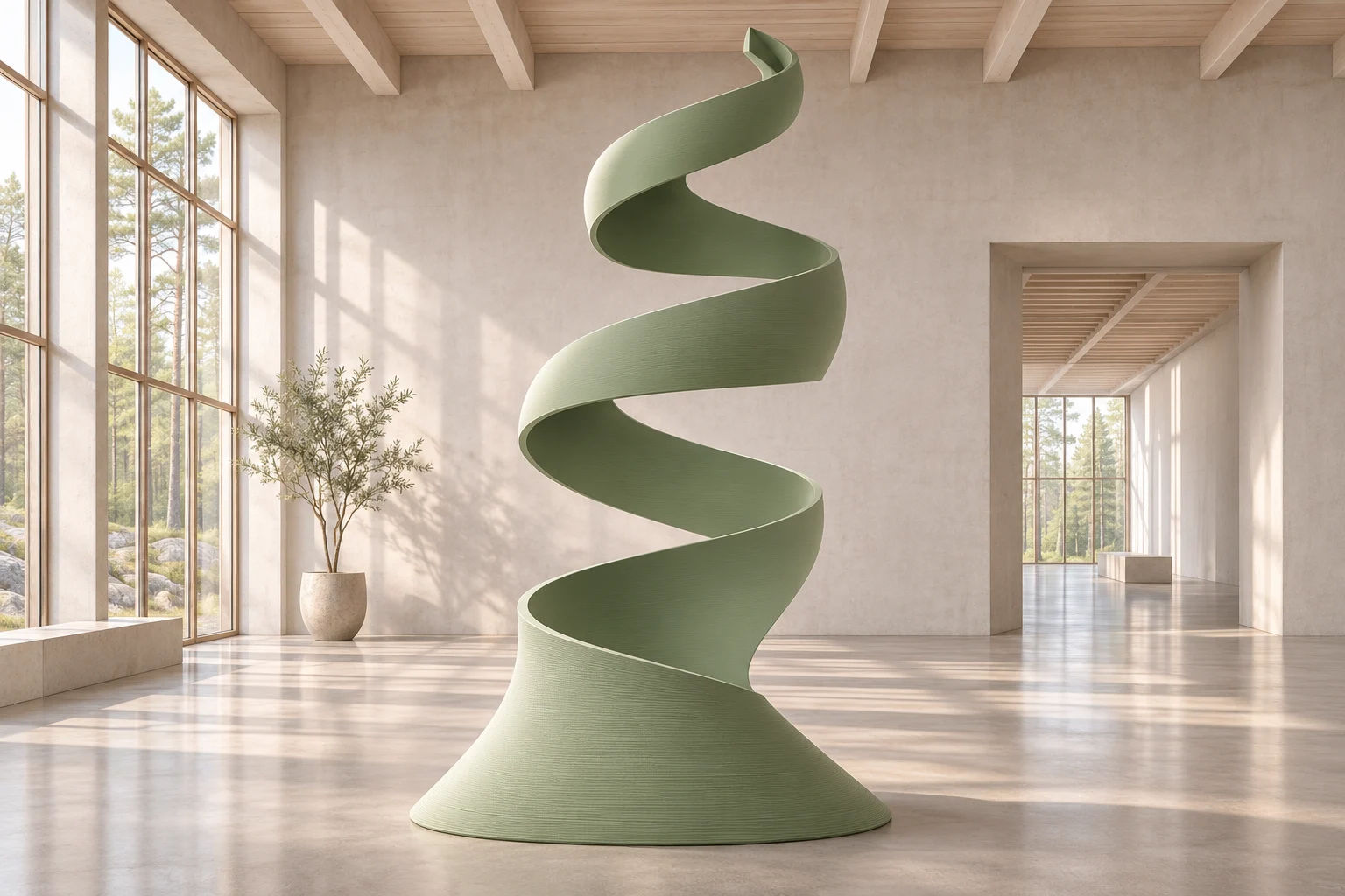
AI-generated concept illustration
AI Design & Engineering
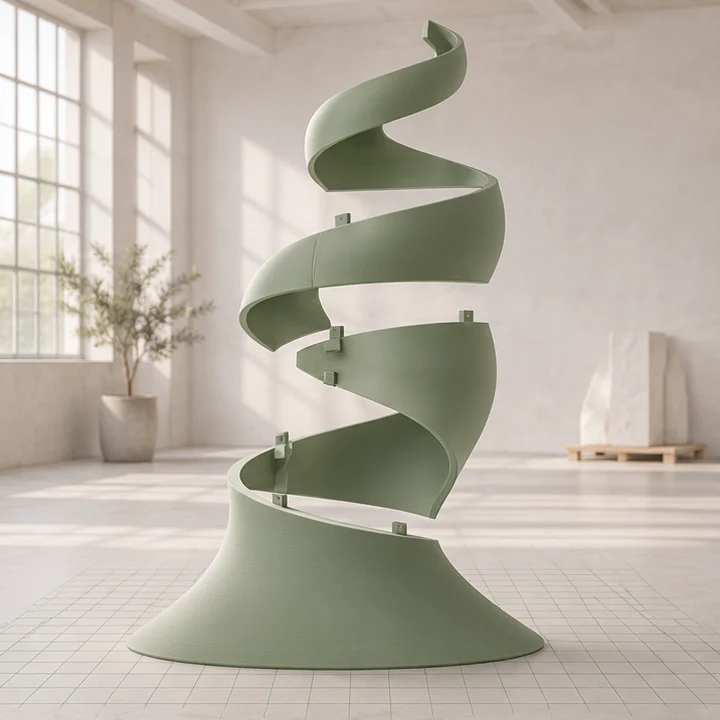
Start with a brief, reference images, sketches or an existing 3D model. Use AI-assisted modelling and iteration to develop the form, then check and repair meshes, adapt wall thickness and split the shell to fit the printer. Plan alignment features, seams and frame clearances. The intended output is a set of numbered, printable parts.
AI-generated concept illustration
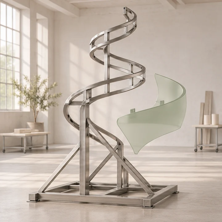
Structural Frame System
Plan the internal steel layout around the shape, weight, supports and installation conditions. Coordinate profiles, cut lengths and angles, joints and fixing points with the shell. The planned outputs include a steel bill of materials, cut list, numbered frame parts and assembly drawings.
AI-generated concept illustration
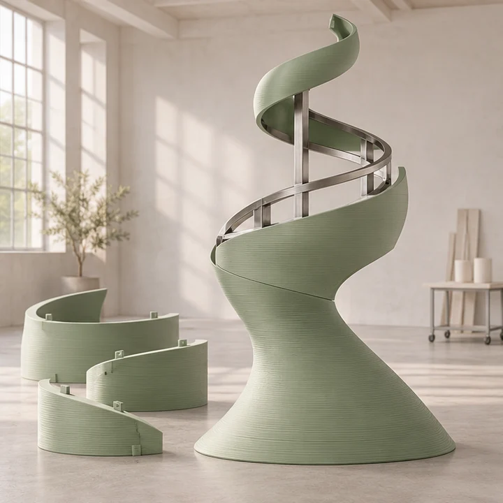
3D Printing & Assembly
Plan print jobs around build volume, material and process. Package the numbered parts with a production sequence and instructions for finishing, fitting the shell to the frame, quality checks, transport and on-site assembly.
One model for the shell and the frame.
The two engineering tracks share dimensions, installation points, joining clearances, tolerances and assembly order. A change to the form can be reviewed against both tracks before the production files are released.
Shared digital project model
Approved form, target dimensions, material assumptions and installation conditions.
Engineers and fabricators review the package before printing, steel fabrication, finishing and assembly.
A three-metre sculpture.
Illustrative workflow · An abstract sculpture for an indoor exhibition.
01
Define the form
Use a sketch or model, the target height and the installation site to agree on a full 3D form.
02
Split the shell
Place seams and joints to suit the printer, appearance and handling of each piece.
03
Coordinate the steel frame
Check fixing points against the shell and assign each steel member an ID, length, cut angle and joint.
04
Review the manufacturing pack
Check print parts, drawings, steel cut list, BOM and assembly order before fabrication.
Who it’s for.
Exhibition & event fabricators
Plan parts around production, transport and installation at a venue.
Interior & spatial designers
Coordinate custom centrepieces with the dimensions and constraints of commercial interiors.
Sculpture studios
Develop an artist’s approved form into components that can be fabricated and fitted together.
Art fabricators
Coordinate polymer shells, steel fabrication and assembly across specialist teams.
The first version in development.
Initial focus
Decorative sculptures around 1–5 metres for indoor commercial spaces, exhibitions and bespoke studio projects. The size range is a development target, subject to validation. The working concept combines a printed polymer shell, an internal metal frame, finishing and assembly.
Longer-term direction
A repeatable production system combining software, engineering workflows and suitable equipment. Large-format filament extrusion (FDM) and pellet extrusion (FGF) are candidates for evaluation. Potential delivery models include tool licensing and project-based fabrication as the workflow is validated.
Outdoor & public work
Larger outdoor installations and public art are longer-term areas of exploration, with project-specific engineering requirements.